Review - Motherboard Gigabyte GA-Z87X-OC

Last generation saw a new type of product in motherboards: the cheap OC oriented SKU. At $200-250 we had a single option specifically designed for OC. This generation, we have several options around that price point, but the GIGABYTE Z87X-OC which we are reviewing today hits it on the nose, or even with a small discount to $186 from time to time.
The purpose of an overclock oriented motherboard is multi-pronged. One the one hand, at this price point, it provides an outlet for extreme overclockers using sub-zero temperatures to get many of the overclocking features they require. It will have several specific features for this crowd and perhaps even specific hardware – but the BIOS and software are all written with them in mind. The other prong is for Joe Public, who might want a nice overclocked system but still to have all the day-to-day features needed. Joe might not use on-board overclocking buttons or the added hardware, but with a backbone for a daily OC he/she wants something built to withstand.
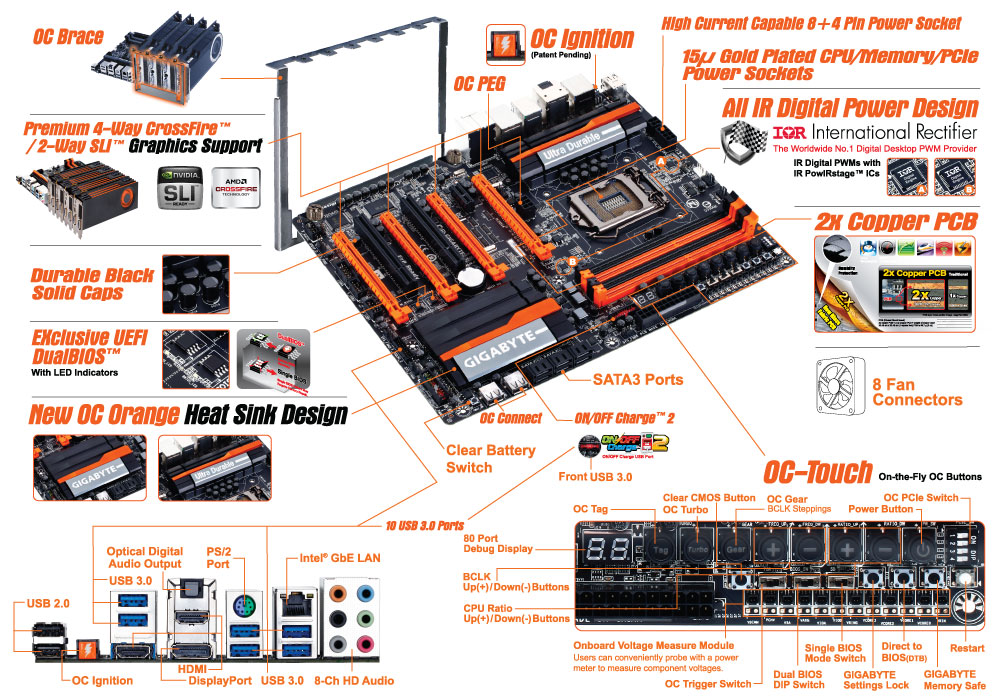
The Z87X-OC is one of two overclocking oriented boards produced by GIGABYTE this generation – the other is the bigger brother, called the Z87X-OC Force. The OC Force is double the price but features four-way SLI (due to a PLX 8747 chip), twice as many power phases (which are not cheap), added SATA/USB controllers and a combination air/water power phase cooler. The Z87X-OC which we are reviewing today could be considered a cut down version of the OC Force, although the Z87X-OC has that price point purpose that proved so popular with Ivy Bridge and Z77 motherboards. It also features some interesting ideas such as the OC Brace and the OC Ignition switch, both unique to GIGABYTE, an extensive array of overclocking buttons (OC Touch) and an interesting placement for USB ports.
GIGABYTE Z87X-OC Overview
It is hard to pin down what exactly I would want in an overclocking motherboard. There are a number of elements that would be beneficial to a daily overclocked system but not an extreme overclocking (sub-zero) setup and vice versa. The trouble with making an overclocking motherboard is that it has to do both – you cannot sell purely to one crowd. Beyond that, it all comes down to potential compromise and how to deal with it.
With the GIGABYTE Z87X-OC, there are a number of features which fit solely into that extreme overclocker crowd: the OC Touch buttons for on-the-fly overclocking, easy voltage monitoring points, PCIe switches, the OC Brace to align graphics cards properly and OC Ignition to allow the chipset (and GPUs/fans) to remain spinning when the system is turned off. Arguably none of these are of use to most daily setups. However we do get OC Connect (the name for the internal USB ports), a dual BIOS system, overclocking oriented power delivery and a PCIe layout suitable for up to four AMD GPUs (or two NVIDIA in SLI), all of which is beneficial to a daily system.
The poignant part of the Z87X-OC is the price. It comes in at $200 for a lot of extreme overclocking oriented features that do not appear on any other motherboard in this price range (or require spending almost double). There are a few cutbacks for that price, namely the audio codec is an ALC892 (rather than ALC898 or ALC1150 at this price point), there are no additional SATA controllers and for some reason only two of the chipset USB 3.0 ports are used. There are two USB 3.0 hubs for another eight USB 3.0 ports, and it seems GIGABYTE went this way to avoid any issues relating to the early chipset revisions and USB 3.0.
In terms of benchmarking results, there is little to separate the Z87X-OC on performance from the expected norm: we get MultiCore Turbo when XMP is enabled to give a full Turbo mode no matter what the load the CPU has. For our daily overclocking we hit the same speeds as other models due to our limited CPU sample, but the process of getting there was rather easy. GIGABYTE is now fully onboard with their new HD BIOS and EasyTune revisions, designed to make adjusting features easier than before.
If we were to suggest modifications, it would be aimed at getting the BIOS to report in 60Hz rather than 30Hz, and that in order to implement the Auto Overclock tuning I would suggest moving the requirement to install Flash. That being said, the auto overclock ended up being very aggressive, causing the system to overheat and de-clock as a result.
The argument can be made for motherboards in this price range that have more features (more SATA 6 Gbps ports, more NICs, WiFi, better Audio), but ultimately GIGABYTE are aiming more for that extreme overclocking crowd that likes to take temperatures below sub-zero. For them, the GIGABYTE Z87X-OC is geared up to take world records and challenge one or two.
Visual Inspection
As mentioned, the first element that strikes me when I look at the Z87X-OC is the orange four PCIe slots, followed by the OC Touch buttons on the top right and the OC Connect USB ports next to the SATA connectors. The heatsinks also exhibit GIGABYTE’s new design for Z87.
With this being an OC oriented board, the socket area is designed to be as empty as possible for sub-zero preparations. The VRM cooler is low profile enough to not interfere with large coolers – part of this comes from using the IR3553 40A ICs in the power delivery, which GIGABYTE are keen to point out run very cool. These are interestingly enough paired with 60A chokes, which seems a little odd if the choke has a larger range than the VRM. I asked GIGABYTE’s experts on the matter, and the answer ultimately comes down to sub-zero cooling. For day-to-day use, the power delivery is unlikely to bump past 25% of the peak capability, and while 40A ICs and 40A chokes might offer a higher peak current under extreme cold, at these temperatures electrical noise is also an issue due to lower resistance, and any temperature loss causes that noise. By using a choke that is designed to output less heat when pushed to the limit, and as 60A chokes are often custom made to the buyer’s requirements (so I am told), it can reduce the potential for noise, albeit under sub-zero cooling only. For the 60A IR3550 ICs, due to their cost, users would require the Z87X-OC Force, the upgraded model.
In order to boost the power delivery to the socket for extreme overclockers there is an 8-pin and an additional 4-pin CPU power connector, whereas in this price bracket we usually get a single 8-pin. Fan headers are abundant, with the Z87X-OC having eight in total and five being in the socket area. At the top we have a 4-pin CPU_Fan and a 4-pin CPU_OPT, the latter being designed for AIO liquid cooling setups. To the right of this is a 3-pin, below the VRMs is a 4-pin and below the 24-pin ATX connector is another 3-pin for the socket area. The final three headers are on the bottom of the board, all 4-pin.
The memory slots use a single sided latch mechanism, which I happen to like although I have seen forum issues where users do not push the memory fully down or miss the click of ensuring the memory is seated properly. For motherboards like the Z87X-OC that have a PCIe x16 as the first full length slot, I would suggested going with single sided latches otherwise a GPU can get in the way when trying to properly adjust memory.
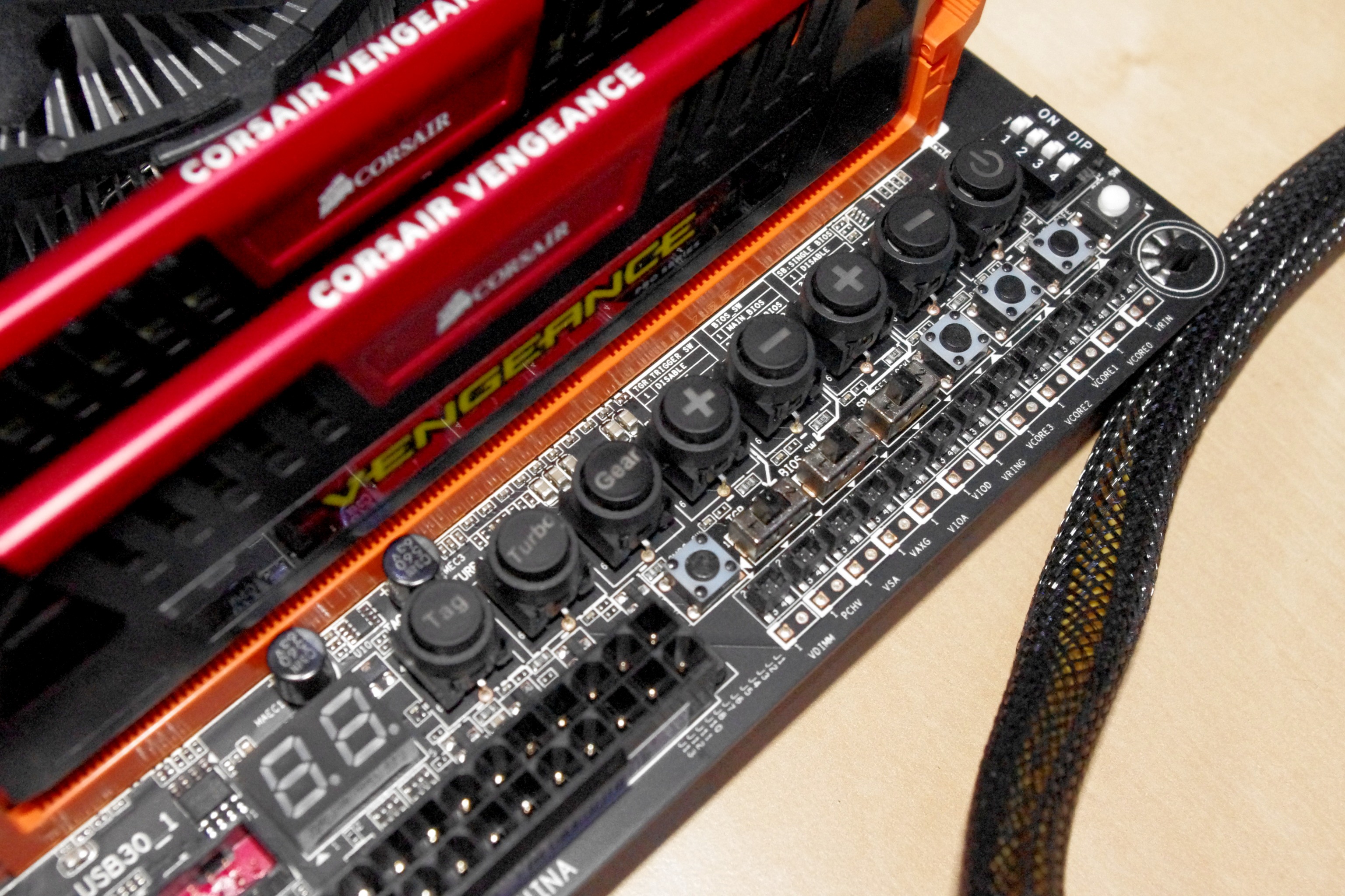
OC Touch
One of the big features of this generation of GIGABYTE overclocking motherboards are the OC Touch buttons, along with voltage read points, PCIe switches and BIOS selection.
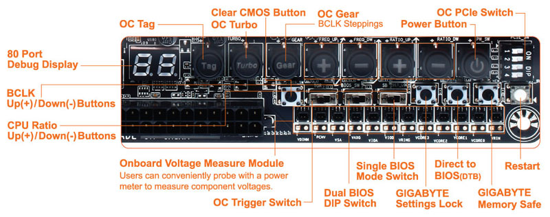
With these buttons extreme overclockers can overclock on the fly, switch BIOSes to one that is more suited to a benchmark, drop the memory to stock levels without adjusting the rest of the settings, enable/disable PCIe switches to remove instability and for Win8 overclocking go straight to BIOS while still having a fast boot sequence. So while these buttons are great, the issue I had was that unless you knew for sure which button was which, it was a little frustrating to bend over the board and try and read the PCB writing to discern one option from the next. GIGABYTE has made a large effort to ensure a lot of writing on the PCB to make it easier, although due to space limitations there are a few arrows pointing to options further away. Perhaps some sort of plastic overlay might be easier?
Below the OC Touch is our Intel USB 3.0 header, shaded red, and then the SATA ports. GIGABYTE are using six from the PCH, all SATA 6 Gbps, leaving the two FlexIO ports optional with PCIe 2.0 as the PCIe option. Below the SATA ports are two USB 2.0 headers, part of the OC Connect feature, which are for overclockers to plug in USB keys / peripherals. If an overclocker has their setup to their left, in order to plug in a USB they have to stretch over to the rear IO in order to do so, which could cause something to move that should not. There is another use for these USB ports – software that requires a USB dongle license (such as Cubase) can be placed here inside the case so others cannot remove it / think it is a USB stick.
The chipset heatsink exhibits GIGABYTE’s new heatsink design, this time in orange, and it grooved with a few fins to help with heat dissipation. Underneath this is the usual array of bottom IO headers – from left to right: front panel audio, 4-pin fan, COM, USB 2.0, USB 2.0, 4-pin fan, USB 3.0, 4-pin fan, and finally the front panel header.
In terms of the PCIe layout, GIGABYTE has gone with the full complement possible from Z87 without using a PCIe switch – x8/x4/x4. This means the first slot is PCIe x16, and the third slot is for the next x8 card. Between the two is the x4 causing an x8/x4/x4. The fourth PCIe slot on the bottom of the board is a PCIe 2.0 x4 from the PCH, meaning we have an “x8/x4/x4 + x4” setup. For gaming:
- CrossFire has no PCIe lane restrictions, and can run quad-CFX at x8/x4/x4 + x4
- SLI requires an x8 from at least the CPU or a PLX, so we are limited to two-way SLI
- SLI requires an x8 from at least the CPU or a PLX, so we are limited to two-way SLI
One of the criticisms that come from motherboards with an x8/x4/x4 layout is that when using two-way SLI, nothing can be used in the third slot otherwise it disables SLI (by shifting the second GPU down to x4). In GIGABYTE’s layout on the Z87X-OC, users can have two-way SLI using PCIe lanes from the CPU and still use the x4 from the PCH for sound/RAID/other PCIe cards.

The final element of the visual inspection is the Rear IO panel, which throws up a couple of surprises of its own. The first is the big orange button, known as the OC Ignition button. This button, when depressed, ensures that the chipset is still powered when the machine is switched off but still plugged in. This allows the fans connected to the headers as well as GPU fans to keep spinning, letting the system cool down / remove moisture in a sub-zero setup between boots.
Aside from OC Ignition, the rear IO is a little different by supporting two HDMI ports (both outputs). By switching from a DVI to a HDMI saves space on the rear IO, making sense when fitting in custom features like OC ignition. Also of note is the audio codec – a Realtek ALC892. At this price bracket we have ALC1150 enabled motherboards, or even ALC898, which are both shown to have higher dynamic range and marginally better distortion numbers. The reason is purely cost for the OC features, where extreme overclockers are not fussed about the codec. Audiophiles notice the difference, and GIGABYTE likes to direct these users to the G1 range of motherboards built with audio in mind.
OC Brace
The final hardware feature which is not on the motherboard directly is the OC Brace included in the box. This addition is designed to be put on a motherboard to allow overclockers to set up their GPUs properly with spacing, rather than having them all fall into each other (useful if you’re managing 3kg copper pots). The OC Brace went through several rounds of design in order to make it able to be quickly fitted, have the back place of the GPU in the right location and for nothing to scratch each other. I used it while testing in my review, and I would happily use it again. I found it a little annoying to put on the motherboard (I kept dropping screws) but once applied it did make it easy to keep GPUs correctly spaced. The only downside is for users that already have a bench table (DimasTech, CoolerMaster etc.) that already have this functionality, or already have something in place of the mounting holes.
Specifications
| CPU |
|
| Chipset |
|
| Memory |
|
| Onboard Graphics | Integrated Graphics Processor:
|
| Audio |
|
| LAN |
|
| Expansion Slots |
|
| Multi-Graphics Technology |
|
| Storage Interface | Chipset:
|
| USB | Chipset:
|
| Internal I/O Connectors |
|
| Back Panel Connectors |
|
| I/O Controller |
|
| H/W Monitoring |
|
| BIOS |
|
| Unique Features |
|
| Bundle Software |
|
| Operating System |
|
| Form Factor |
|


0 komentar:
Post a Comment